How to Pimp My Bitaxe

In this guide, we’ll walk you through the installation of the “Pimp My Bitaxe” upgrade kit step by step.
Good news: this guide also works great for other cooling upgrades – the basic steps are pretty much the same. Sure, some other heatsinks might require different adapters, but don’t worry – with this guide, you’ll handle it like a pro!
⚠️ Important: Replacing the heatsink involves mechanical work on your Bitaxe. Make sure to disconnect the device from power beforehand and proceed with caution.
We are not liable for any damage caused by improper handling during the upgrade.
In short: use common sense, treat your Bitaxe with care – and don’t break anything! 😉
Which upgrade kit would you like to install?
Pimp My Bitaxe Upgrade Kit Basic – Schritt-für-Schritt Installationsanleitung 🚀
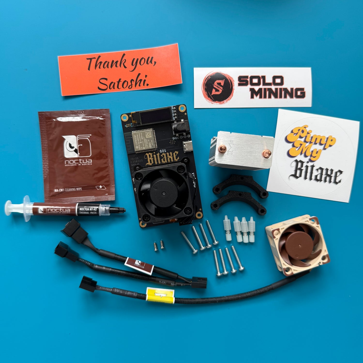
1. Check the package contents
Check if all parts are included in the package.
For the complete set, the following items should be included:
- ICE-Tower heatsink
- Mounting adapter for the ICE-Tower heatsink, including 4 push-pins for securing it to the Bitaxe
- Noctua fan NF-A4x20 5V PWM
- Y-splitter cable
- Thermal paste and cleaning cloth for the old thermal paste
- 8x M3x20 screws
- 2x M2.5x6 screws for the heatsink adapter

2. Apply the stickers
Take the stickers out of the box and stick them somewhere right away - like on your laptop, for example.

3. Remove the old heatsink
Carefully disconnect the fan connector.
Then loosen the 4 screws that held the standard heatsink in place.
Once the pins are removed, the heatsink can be easily lifted off.

4. Clean the ASIC
Clean the old thermal paste from the chip.
Use the included cleaning cloth to easily remove the old thermal paste from the chip.
Additionally, you can use cotton swabs or a soft cloth with IPA cleaner for a more thorough cleaning.
WARNING!!!
This step applies mechanical pressure to the soldered ASIC chip. Please be as careful as possible and never press forcefully on the chip, as this could damage it.

4.1 Milestone reached
This is how the ASIC chip should look after cleaning. Make sure that no fibers from the cleaning cloth or cotton swabs are left on the chip.
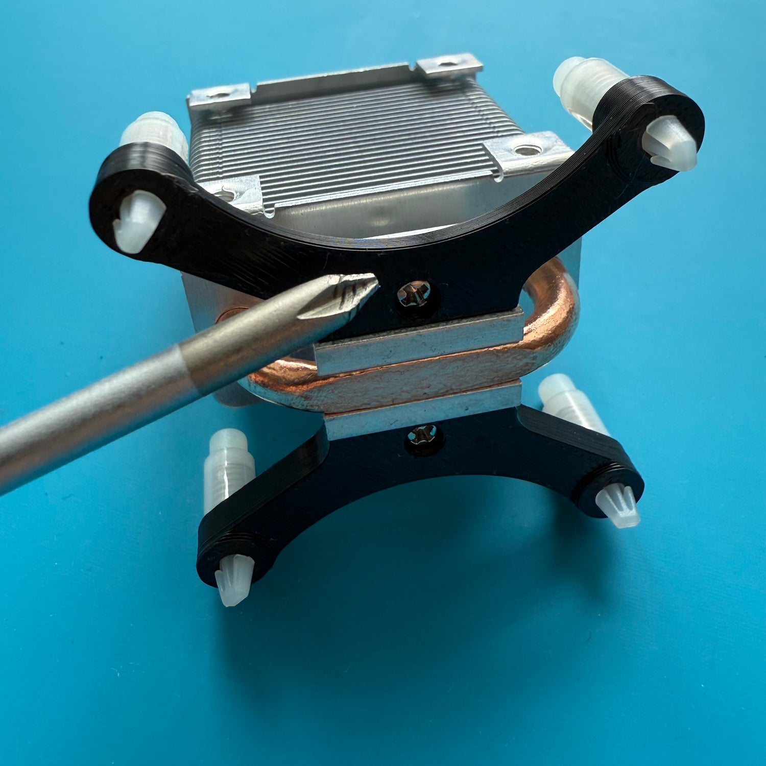
5. Installing the heatsink adapter
Push the 4 push-pins through the 3d printed adapters as shown in the Photo.
Use the two small M2.5x6 screws to screw the adapter to the bottom of the heatsink.
Make sure the adapter is mounted in the correct orientation. The screws should fully sink into the adapter - if they do, you’ve attached it correctly.
Many thanks to IN ∞/21M WE TRUST. for the design and permission to use it!
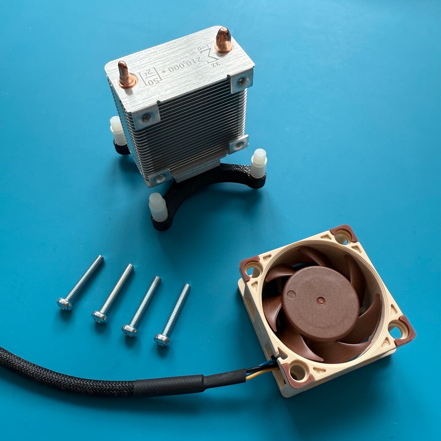
6. Attaching the fan onto the heatsink
Use four of the included M3x20 screws to securely mount the fan onto the heatsink.
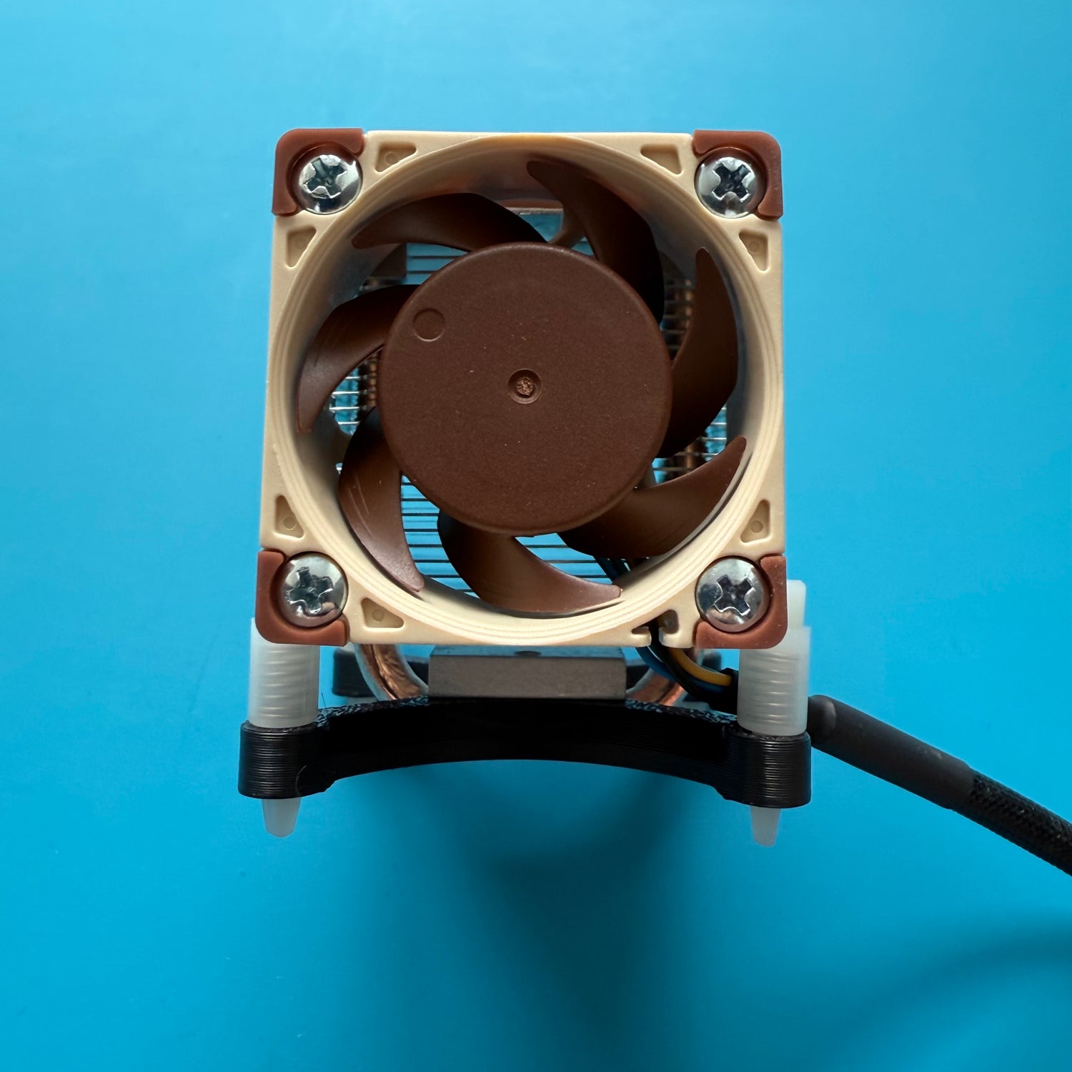
6.1. After attaching the fan
This is how the heatsink should look with the mounted adapter and fan.
We have had good experiences with the cable routing shown here. However, there are no strict rules for cable management - other routing methods are also possible.

7. Applying the thermal paste
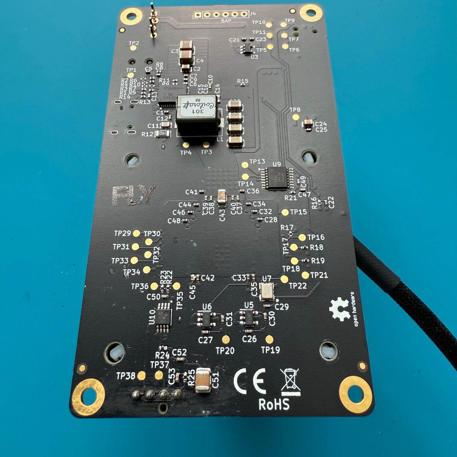
Using the syringe, carefully apply a pea-sized drop of thermal paste onto the ASIC chip.
The correct amount of thermal paste is shown in the reference image. Try not to use too little, but also avoid excessive paste.
8. Attaching the heatsink onto the Bitaxe
We recommend installing the heatsink with the fan facing upward to ensure optimal temperature management.
In its pre-assembled state, you can place the heatsink on a table with the contact surface facing up. This allows you to easily position the Bitaxe from above, aligning it correctly with the four push-pins.
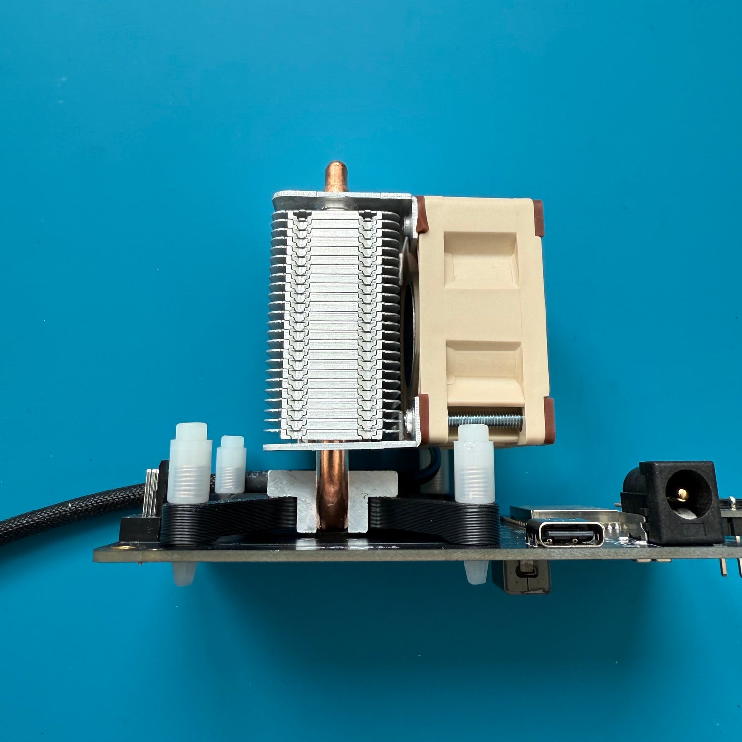
Now, gently press all four pins through the corresponding holes on the Bitaxe. It is best to start with two diagonally opposite pins, then insert the remaining two.
8.1 Final Assembly Check
This is how the setup should look once all four push-pins are correctly inserted through the board and have each clicked into place.
Alternatively, you can use screws and nuts instead of push-pins. However, be very careful when tightening them - applying too much pressure on the ASIC chip could cause damage.
9. Connecting the fan
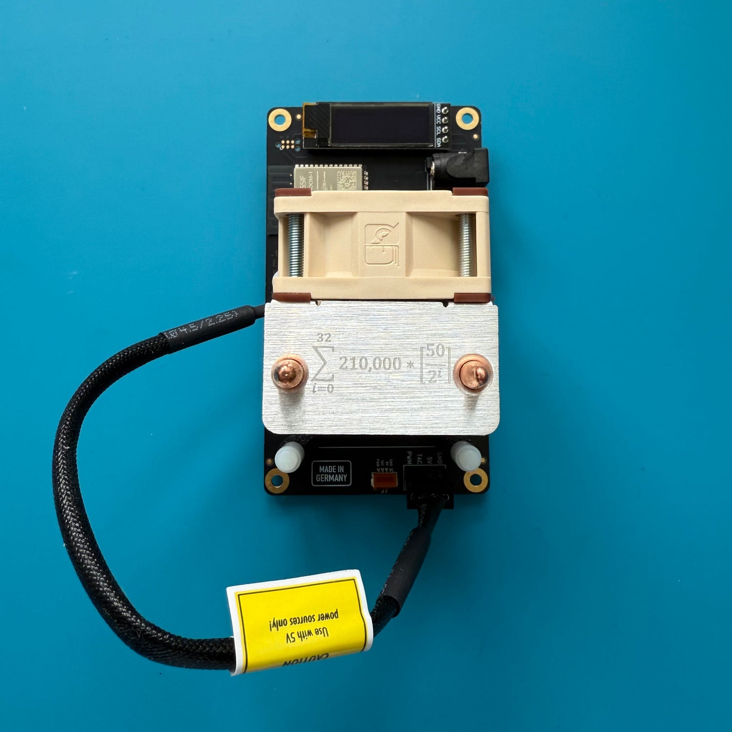
If no rear fan is being installed, simply connect the fan to the board now.
Optionally, you can tidy up the cables using zip ties. You may also remove the yellow sticker on the fan cable for a cleaner look.
Without a rear fan, this concludes the installation guide. Enjoy your pimped Bitaxe!
10. Installing the second fan on the back
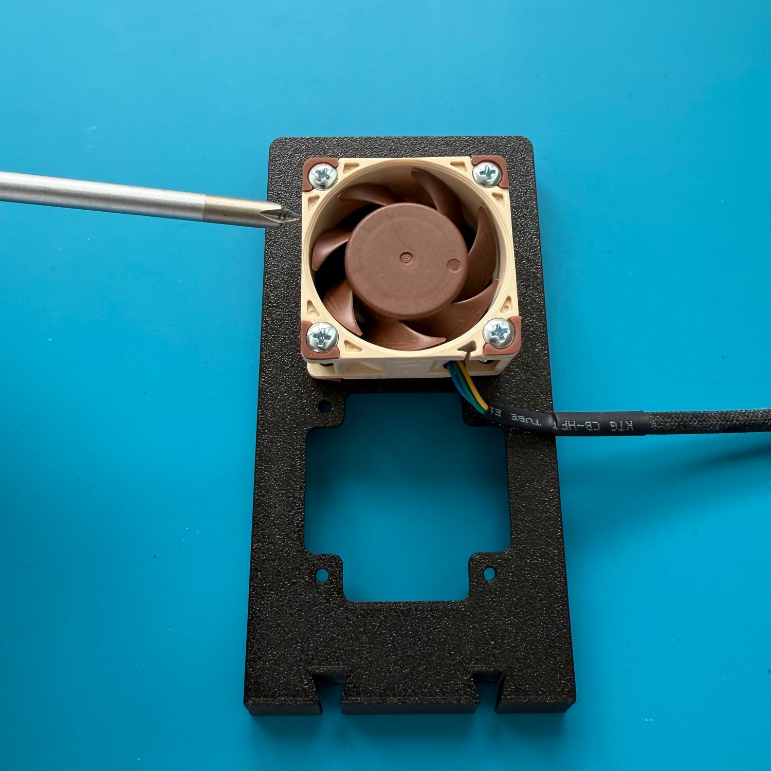
Use the remaining four M3x20 screws to secure the second fan to the back of the mount. We recommend placing it in the upper position, as this is where the voltage regulator, which requires the most cooling, is located.
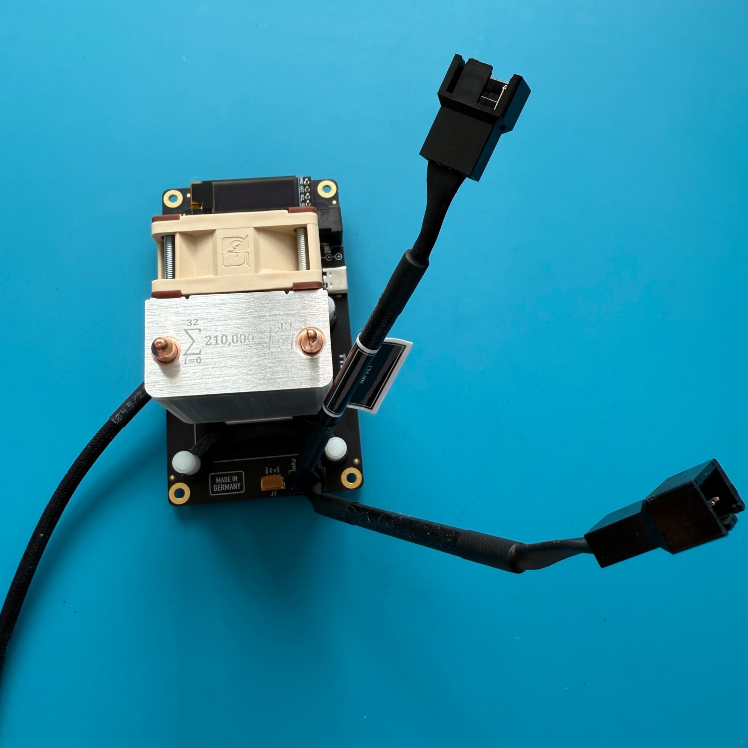
11. Connecting the Y-splitter cable
The included Y-splitter cable can be easily connected to the corresponding fan connector on the Bitaxe. It doesn’t matter which end is connected to the front or rear fan - both will work the same way.
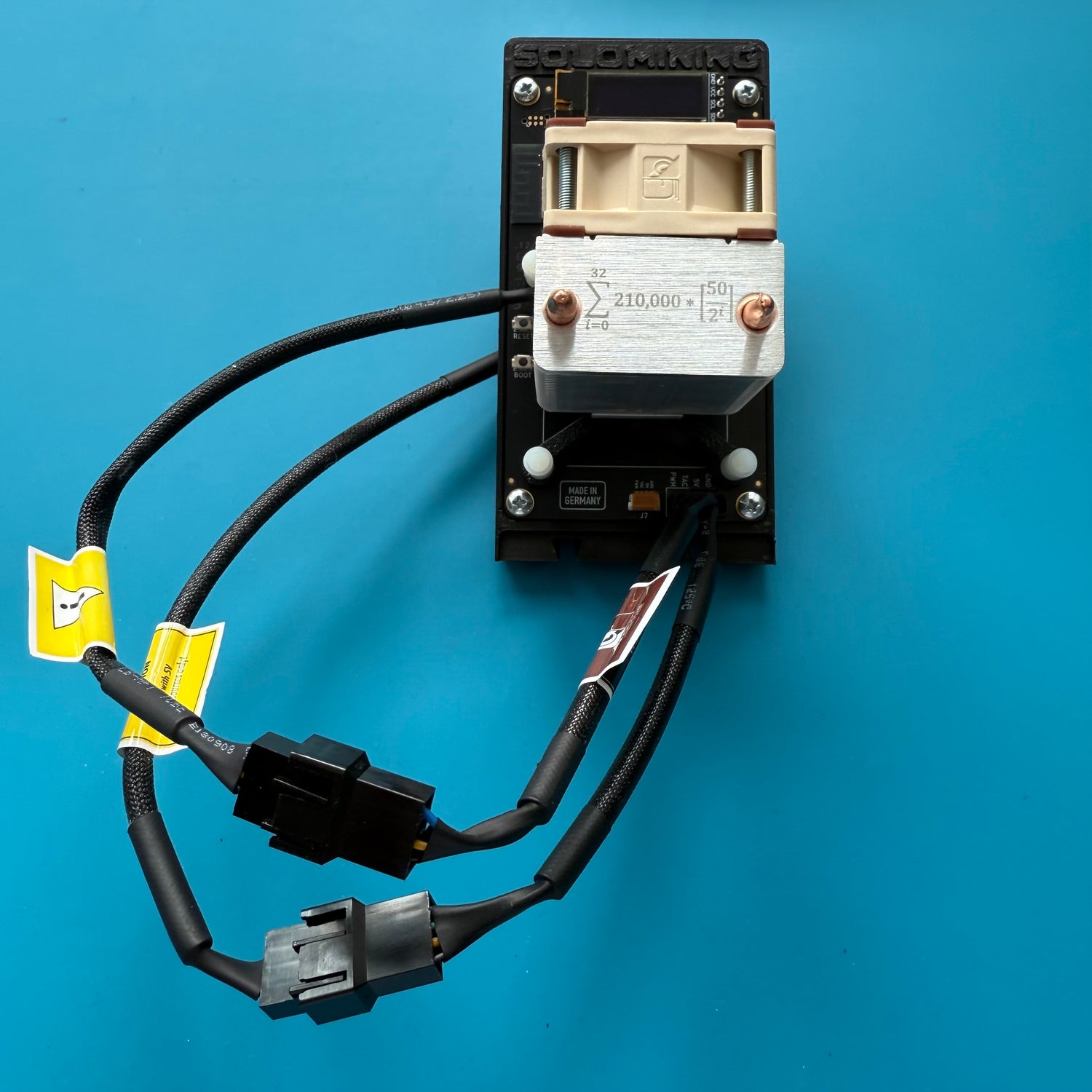
12. Mounting the backplate and connecting the fan cables
In this step, the Bitaxe can be screwed onto the backplate of the mount. Use the four small screws included with the mount for this. Next, connect the front and rear fan cables to the Y-splitter.
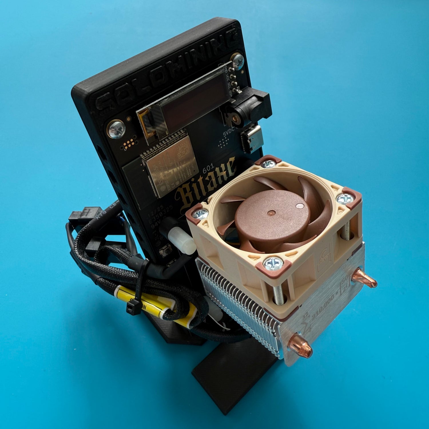
13. Cable Management
Once all cables are connected, they can be neatly bundled together. You can use a zip tie (not included in the set) or a wire (e.g., from the power supply) for this.
There are no strict rules for cable management - feel free to get creative! Just make sure that the cables do not come into direct contact with the board to avoid potential issues.
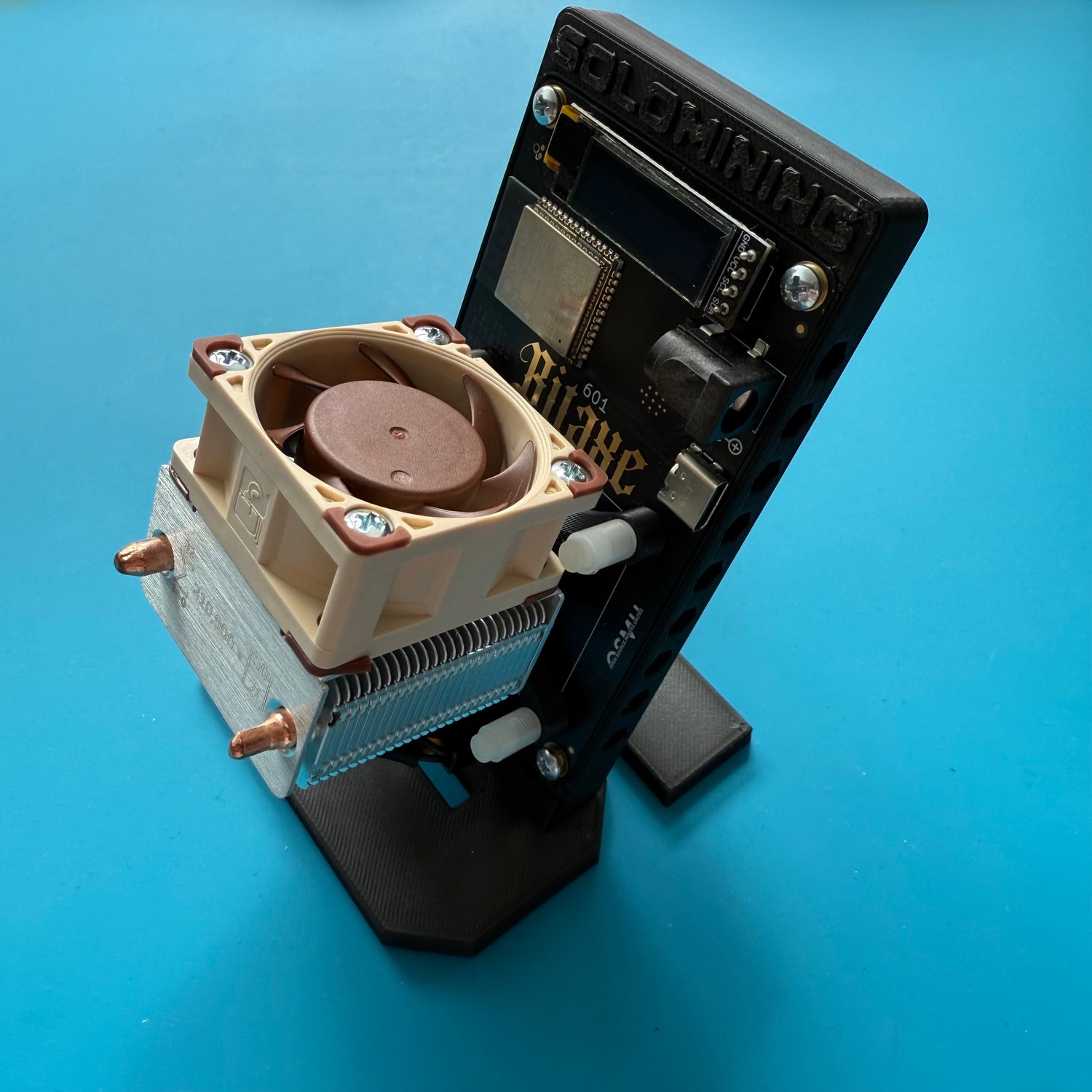
14. Done
Everything is now set up - your Bitaxe has been successfully pimped and will no longer have overheating issues. Enjoy the improved cooling performance!
Note:
The standard power supply provides 31.2 watts of power. For long-term use, it should not be operated at more than 80% load, which corresponds to a maximum power consumption of 25 watts. Keep this in mind if you plan to overclock your device.
Pimp My Bitaxe Upgrade Kit Premium – Schritt-für-Schritt Installationsanleitung 🌟

1. Check the contents of the package
Check if all parts are included in the package. For the Premium Set, you should have:
- 1x ICE-Tower Low-Profile Plus heatsink
- 2x Mounting adapters for the heatsink incl. 2x M2.5x6 screws
- 1x Noctua NF-A6x15 5V PWM fan
- 1x Mounting adapter for the fan incl. 2x retaining clips
- Thermal paste incl. cleaning wipe (not shown in the photo)
- 4x M3x12 screws incl. 4x M3 nuts

2. Unplug fan
Unplug the connector of the old fan.

3. Loosen the screws
Carefully loosen the 4 mounting screws of the standard heatsink on the back side.

4. Remove the heatsink
Once the four mounting screws are loosened, the heatsink including the fan can be easily removed from the Bitaxe.

5. Cleaning the ASIC chip
Use the included cleaning wipe to easily remove the old thermal paste from the chip. If you want to be extra thorough, you can also use cotton swabs or a cloth with IPA cleaner. Make sure no lint is left on the chip.
⚠️ Important: This step applies mechanical pressure to the soldered ASIC chip. Please be very careful and never press down forcefully – otherwise the chip could be damaged! So take it easy and go gentle. 😉

6. Milestone reached
Your Bitaxe is now free of the old heatsink, and the ASIC chip is clean. Now we’re ready to start installing the upgrade kit!

7. Installing the mounting adapter
Screw the two mounting adapters onto the heatsink using the included M2.5x6 screws.
Big thanks at this point to IN ∞/21M WE TRUST. for the awesome design and the permission to use these adapters! 🙌

8. Fan and heatsink
For the next steps, you’ll need:
- the heatsink
- the fan
- the fan adapter
- the two retaining clips

9. Attach the fan adapter
Place the adapter onto the heatsink as shown in the photo.
🔍 Note: The heatsink is not square – the adapter only fits in one specific orientation. If it doesn’t fit right away, just give it a turn!

10. Attach the fan
Place the fan loosely onto the adapter – no worries, it’s not firmly attached yet and can be a little wobbly at this point. Everything will fall into place soon!

11. Orient the fan correctly
Make sure the fan is oriented as shown in the photo – the sticker with the model label should be facing upwards.
Only in this position will the fan properly draw in the warm air and blow it away from the heat source.

12. Secure the fan
Use the two retaining clips to attach the fan to the heatsink, as shown in the photo.
First, insert both ends of the clip into the designated holes on the fan, then gently push the clip under the heatsink.
💡 Tip: This is the trickiest part of the entire installation – so take your time and work carefully with a bit of patience and finesse. You’ve got this! 💪

13. Milestone reached
Congrats! You’ve completed the trickiest part. The assembled unit of heatsink and fan should now look like this.

14. Final stretch
Now we’re on the final stretch. Next, we’ll show you how to mount the heatsink onto your Bitaxe.

15. Apply thermal paste
Using the syringe, carefully apply a pea-sized drop of thermal paste directly onto the ASIC chip.
How much exactly? Take a look at the photo – it shows the ideal amount. Don’t skimp and don’t overdo it – this exact amount ensures optimal cooling. 🧊

16. Plug in the fan cable
Since the space between the board and the heatsink is quite tight, it’s best to plug in the fan cable now.
Once the heatsink is firmly screwed in, it’ll be much harder to reach the connector – so better get it done beforehand! 🔌

17. Insert screws into the board
To properly align the board over the heatsink, it’s a good idea to insert two of the four screws diagonally from the back of the board.

18. Place the Bitaxe onto the heatsink
Carefully place the board onto the heatsink so that the two screws go directly through the matching openings in the mounting adapter. That way, everything sits exactly where it should – no slipping around. 🧩
🔄 Tip: Align the board so that the curved heatpipes face toward the display – this ensures everything fits together perfectly later on.

19. Insert the remaining screws
Now insert the remaining two screws from the back of the board.
It’s best to gently hold your Bitaxe with one finger while doing this to keep it from tipping forward – a little balance goes a long way!

20. Gently tighten the screws
Hold the M3 nuts under the screws with one finger and gently tighten them by hand – no force needed!
🔧 Tip: It’s best to tighten the screws in a crisscross (diagonal) pattern – this distributes the pressure evenly and ensures everything sits nice and straight.

21. Fully tighten the screws
Use pliers or an M3 wrench to carefully tighten the screws.
🛑 Important: Don’t overdo it! Too much pressure can damage the ASIC chip. Hand-tight is more than enough – better to go gentle than forceful!

22. Done!
🎉 Congratulations!
You did it – your Bitaxe is now successfully pimped and ready for cool, long-term operation. Overheating? Not your problem anymore!
🔌 Note:
The standard power supply provides 30 watts. For safe continuous use, it shouldn’t be loaded beyond 80% – that means a maximum power draw of 24 watts.
If you plan to overclock your Bitaxe, keep this in mind and play it safe.

23. Cable management (optional)
Optionally, you can now neatly secure the fan cable to the bracket – ideally with a small cable tie (not included).
Of course, any creative cable management solution is welcome.
📌 Our recommendation:
Do not run the cable underneath the heatsink or wrap it around the copper heatpipes – this could cause a heat buildup and significantly reduce cooling performance.
